Italiano


                                        DESCRIPTION PANTOGRAPH


Exploded Mechanical Realization


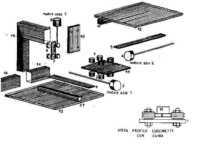
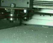
At start i have created the arm (15) necessary to support the milling machine.For his realization i have use a aluminum profile (used from the constructors of tendaggi) who has the advantage of  being very god for the rigid implantation. The arm has been fixed to a multilayer plan (13) on which is fixed the guide (6) for the movement of the axis "Y",putting the guide on a square support of iron  (17). On this guide slide 4 throat bearings  (2) on one iron slab of thickness 4mm (16).


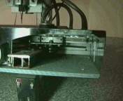
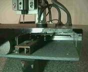
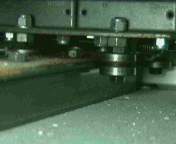
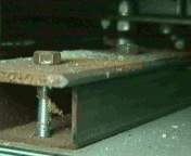
Sight of the below part the job plan
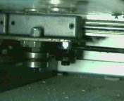
Sight of the throat bearings


On the opposite face of the slab are fixed the throat bearings  (1) in which slide the guide for the movement of axis "X" (5). The guide for the movement of the axis "X", is fixed under the mobile multilayer plan(12).first ,on  this plan are fixed  threads eyelets , to enable the blocking of the piece to work ,with clips formed one by a washer and a screw. 


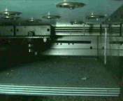
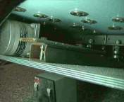
The throat bearings and the guide of precision Up the eyelets are noticed thread you for the implantation of the clips


The milling machine is  fixed to a aluminum slab (10), to which it has been screwed the guide (7), that it slides on 4  throat bearings (8)fixed to a support that  has been blocked to the aluminum arm (over described). The system now is never motor, the mtor  that will have to set in action the mobile plan on the aces "X" "Y", and the milling machine on the axis" Z ". To the motors  have been fastened,  auctions threaded with the diameter of 6 milimeter. The auctions will screw on the dice that have been respective fixed: to the slab door bearings (16) for the aces "X" "Y"e to the vertical guide (7) for the axis" Z ". The part electronic easy realizable (pantograf.zip) is seen the meager number of members and thanks to the program of control (cam_.zip) that it uses the door parallel normally used for printing, without the added one of some card in personal the computer. As far as the program I have decided to realize it for being able to interpret the designs with extension DXF, realizable with all the programs CAD or GRAPHIC(autocad, 3d, coreldraw). The program translate the design realized in commandos for motor the step-step, it is possible to vary the constructive dimensions begins them without some limit in the blowup or reduction. They complete the software the subdirectory : 1) visualization of the designs realizes 2) positioning to you of the tool 3) a program of realization of designs DXF (for who does not possess a program CAD). .
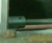
The ear-ring that fastens the auction threaded to the motor.
 
The precision guide
The motor step-step.